説明
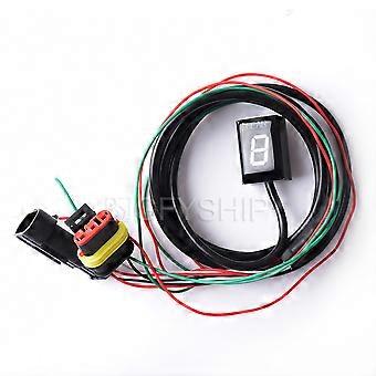
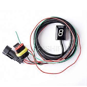
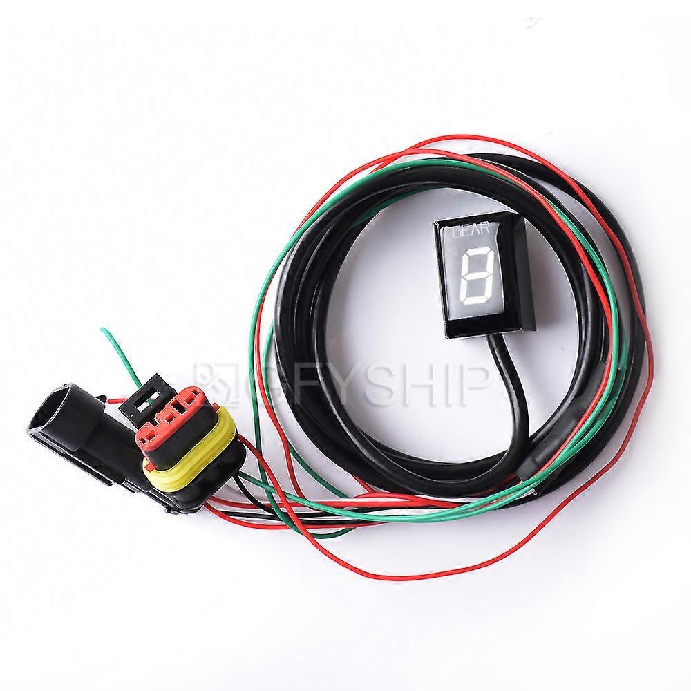
For Ducati Supersport ALL 1999 to 2007 For Ducati ST3 Non ABS 2004-2007 Motorcycle Gear Indicator Digital Gear Meter
Features:
Condition:
Color:Black
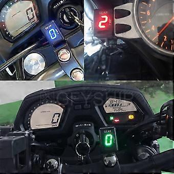
Light Color: Red/Blue/Green
1-6 Gear display
Fitment:
For Ducati ST3 Non ABS 2004-2007
For Ducati Supersport ALL 1999-2007
Installation:
Locate the Speed Sensor connector.
Ducati: The Speed Sensor is mounted at the rear wheel. Trace the cable from the sensor until you find the 3-pole black speed sensor connector. The connector is usually accessible by removing the right side fairing and on most models it is in close proximity of the right side engine cover.
Confirmation:
1. Separate the Speed Sensor connector (you might need to use a small flathead screwdriver to get the connector apart). Rotate the rear wheel while ignition is on. The speedometer should indicate 0. If so, turn the ignition off and proceed to the next step. Otherwise, if the speedometer registers a speed other than 0, you have not disconnected the correct coupler and need to look again.
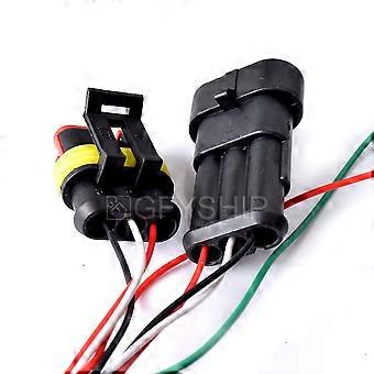
2. After separating the Speed Sensor connector, plug in both the male and female 3-pole GFYSHIP harness connectors. Make sure the connectors are fully seated.
3. Find RPM/Timing Sensor (Pickup) connector. The sensor is mounted either on top, or the side of the crankcase. Trace the cable from the sensor until you find the 3-pole connector.
Here is the connector location on some popular models:
Monster S2R, Multistrada: At the left side, above horizontal cylinder, ziptied to frame.
Monster S4RS: Behind left side cover under seat.
ST3: At the right side of engine, zip-tied to frame.
If in doubt, check the bikes Service Manual or ask your dealer for the location of the RPM/Timing Sensor connector.
4. Disconnect the connector, and pull back the LARGER rubber boot from the plug, to leave the three wires exposed.
5. Route the GFYSHIP Black/Green wire through the rubber boot from the back. Make sure the wire will NOT touch the exhaust pipe or cylinder block.
6. Connect the GFYSHIP Black/Green wire to the wire in connector slot position 1, using the Red wire tap connector supplied.
Usage: Place the unstripped run wire (slot position 1) inside the run channel. Close the side cover until latched. Cut off the excess length, then insert the unstripped tap wire (Black/Green) completely and check its position. Insert the blade (u-contact) and press down by finger pressure. Then, fully depress the u-contact with pliers. Close the hinged top cover until latched.
7. Connect and secure the RPM/Timing Sensor connector with zip-tie.
8. Connect the GFYSHIP Red wire to a switched +12V power lead, e.g. behind the Fusebox to the Red/Back wire.
We recommend to make a temporary connection for the red wire (e.g. by using a thin needle) and see if the display turns on and off with the Ignition Key. Then cut off the excess length from the red wire and use the second Red wire tap connector supplied to make the connection.
Set up
:
You need to setup the module after installation. When ignition is turned on, the display counts backwards (6 to 1) indicating that the memory is clear.
- Raise the rear wheel off the ground by using a stand, and start the engine in Neutral. (If you do not have a stand, you may setup the unit while riding. Find a long, straight road with light traffic.)
- The display will blink 1. Select first gear, release the clutch, and keep the RPM above idle speed. The display is blinking faster while the unit is learning the gear.
- When the display shows 2, select second gear. Repeat this process until all gears are thought (5 or 6). The unit is programmed and should indicate the gears correctly. Now, when ignition is turned on, the display counts forward (1 to 6) indicating that it is fully functional.
Package Include:
1 x
Gear Indicator
(
Contains installation instructions
)
-
Fruugo ID:
313338733-699236888
-
EAN:
592080430896
製品安全情報
以下に概説するこの製品に固有の製品安全性情報を参照してください。
以下の情報は、この製品を販売する独立したサードパーティ小売業者によって提供されています。
製品安全ラベル

安全上の警告:
Not suitable for children under 36 months, Choking Hazard, Adult supervision recommended
材料:
Polymethylsilsesquioxane
メーカー型番:
592080430896
モデル番号:
592080430896
シリアルナンバー:
592080430896
バッチ番号:
592080430896