説明
Specification
Working voltage
Transmitter : 3V (2PCS AAA battery 1.5V LR03) Receiver : 12-24V DC
Working current
Transmitter < 85A, Receiver < 30mA (24V DC)
Photocell wavelength940nm
Angle of emission5
Receiving range> 12m
Relay contact loading capacity1A/30VDC
Size100*40*35mm
Safety Instruction
1.For security. please read the user manual carefully before in1 tial oper ation
2.This photocell is with out any fuse so Please make sure the power is off before installation
3.Only used this system that do not cause any danger life or propety during the running failure or its security risks eliminated
4. Please guarantee the products used in effective working range
User notice
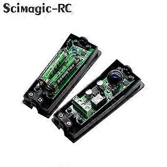
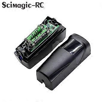
4.1 Receive module J4 in above picture is the option switch for NO and NC of photocell switch.
4.1.1When the short circuit cap on NO.it is normally open.
4.1.2When the short circuit cap on NC.jt is normally closed
4 2 Installation
4.2.1 The photocell should be installed more than 20cm above the ground (to avoid reflection), and th e distance between emitter and receiver should be more than 50cm.
4.2.2 End user should install the photocell receiver on the back of the direct sunlight or other strong light source(5-) to keep photocell work well steadily.
4.2.3 Avoid installing other infrared photocell emitters within the effective distance of receiver.
4.2.4 If the end user need to install other photocells in one same straight line , the receivers could be installed in the two ends and the emitters could be back-to-back installed.
4.2.5 Stable installation could avoid the signal of emitter and receiver skewing due to lightly vibrate and the malfunction.
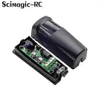
4.2.6 When the product is install in some place with angle , end user could adjust the PCBA to make the installation better.
4.2.7 Connect the power after the inspection, when short circuit cap at NO, After the battery is installed on the LED lamp of the transmitting module, the LED lamp lights up for 0.5 seconds and then goes out, receiver module LED turns on, receiver module contact at off; when make the cap of emitter and receiver in alignment, receiver module LED is off, NC/NO is on ;when something or someone shelter the sensor, receiver module LED will turn on , NC/NO contact is off. When short circuit cap at NC, the state of NO/NO is opposite to the above phenomenon.
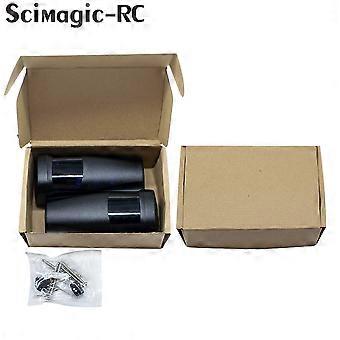
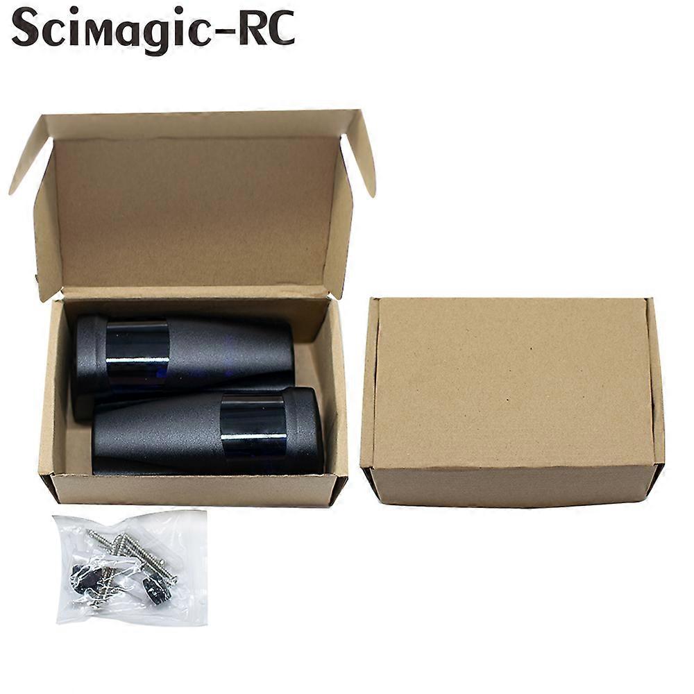
Installation Pictures
1.Open the package and take out the accessories
2. Stick the holder location map where you need
3.Drill holes and fix expansion pipe
4.Connect wires
5. Wiring diagram
6.Fix the screws NO1,2,3 with the base .
7.Adjust the appropriate angle of PCBA(90 ), fix screws NO 4.5
8.Installation of transmitter and receiver completed without wiring
If you need to buy more, you can contact me and I will give you the lowest price.
-
Fruugo ID:
231755327-495092039
-
EAN:
7382840679558
製品安全情報
以下に概説するこの製品に固有の製品安全性情報を参照してください。
以下の情報は、この製品を販売する独立したサードパーティ小売業者によって提供されています。
製品安全ラベル

安全上の警告:
Not suitable for children under 36 months, Choking Hazard, Adult supervision recommended
材料:
Polymethylsilsesquioxane