説明
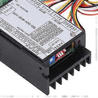
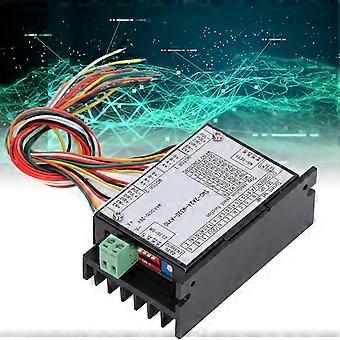
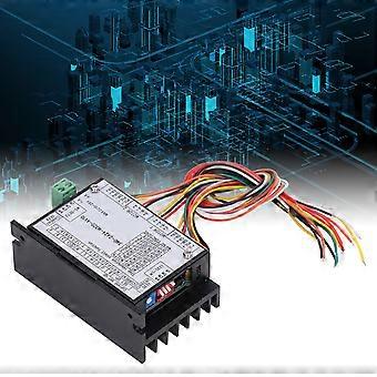
2 Phase 4 Wire Stepper Driver 2 In 1 Bipolar Stepper Motor Drivers Photoelectric Isolation
Item Type: 2 Phase 4 Wire Stepper Driver
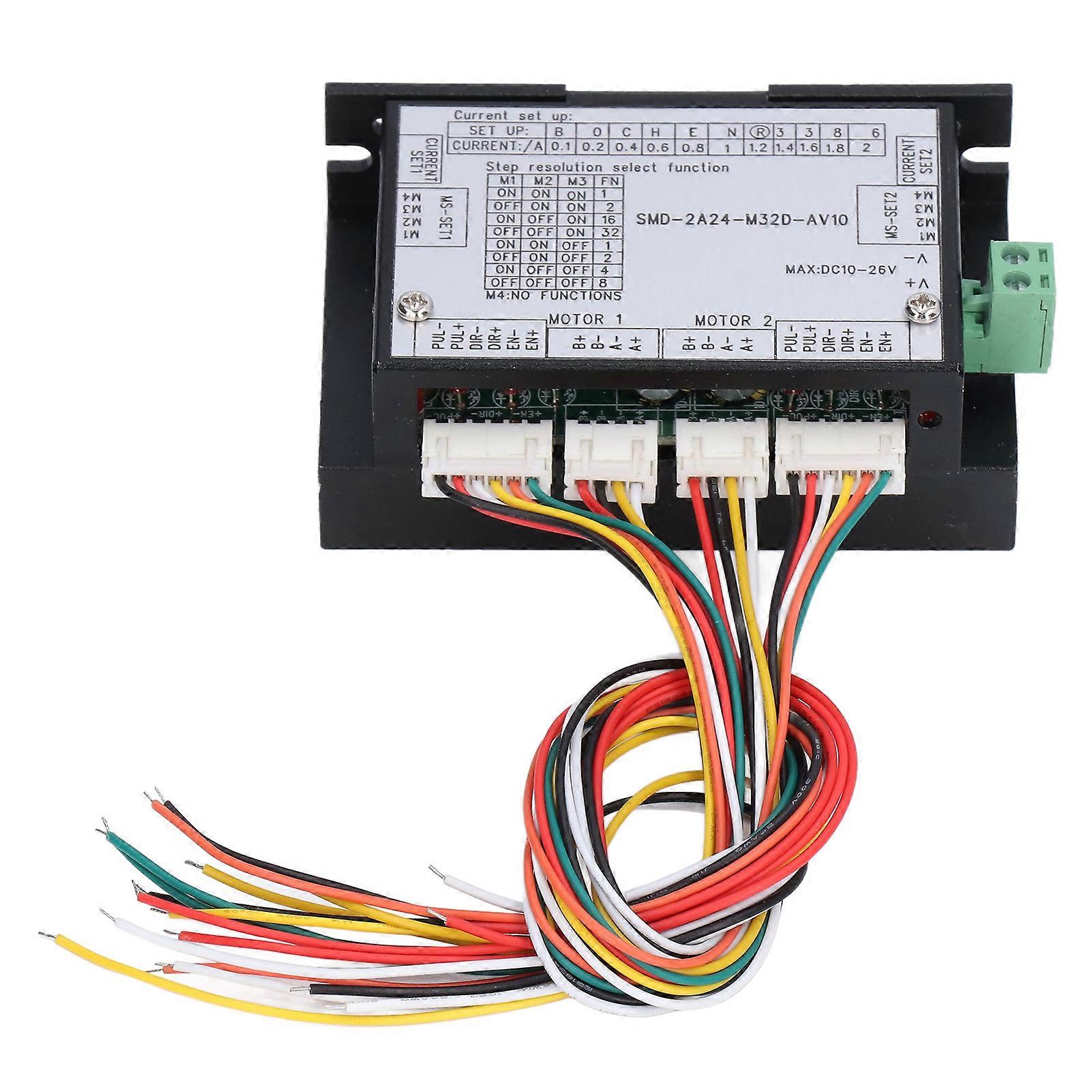
Model: SMD-2A24-M32D-AV10
Material: ABS
Specification: 2 Phase 4 Wire Bipolar Type
Speed Response Rate: 100KHz
Operating Temperature: 0-50
Operating Humidity: 40-90%RH
Input Voltage: DC10V-26V
Minimum Standby Current: 0.03A
Maximum Work Allowable Current: 15A (Motor and Brake 10A + Solenoid Valve 5A)
Allow Start up Peaks Surge Current: 35A 0.2 Seconds
Allowable Input Power Ripple: Less than or equal to 500MV
The transmitting frequency of the light belt is 433MHz, the antenna is 340mm. The transmitting power is 10MW. The open distance is 100 meters.
The remote control antenna of 250mm, receiving sensitivity of -110DB, and open distance of 100 meters.
Solenoid Valve Interface Specifications: Adapt to various standard solenoid valves with 24V and operating current within 5A.
Motor and Brake Interface Specifications: Adapt to 24V electromagnetic brakes and motors, and the total working current does not exceed 10A.
How to Use:
1. Wiring method:
GND: DC power supply ground wire
+V: DC power supply positive pole, range +9V+36V, recommended value +24VDC
A+, A: A phase coil of the motor
B+, B: Bphase coil of the motor
2. Control signal interface function:
PUL+(+5V)/PUL(PUL): Pulse control signal: the rising edge of the pulse is valid, PUL is 4~5V at high level, and 0~0.5V at low level. In order to reliably respond to pulse signals, the pulse width should be greater than 1.2s. If +12V or +24V is used, a series resistor is required.
DIR+(+5V)/DIR(DIR): Direction signal: high low level signal. To ensure reliable commutation of the motor, the direction signal should be established at least 5s before the pulse signal. The initial running direction of the motor is related to the wiring of the motor. Interchange any phase winding (such as A+, A exchange) can change the initial running direction of the motor, 4~5V when DIR is high level, and 0~0.5V when low level.
ENA+(+5V) ENA(ENA): Enable signal: This input signal is used to enable or disable. When ENA+ is connected to +5V and ENA is connected to low level (or the internal optocoupler is turned on), the driver will cut off the current of each phase of the motor to make the motor in a free state, and the step pulse will not be responded at this time. When this function is not needed, the enable signal terminal can be left floating.
Package List
1 x Stepper Motor Driver
Do not place following to other heat generating equipment, avoid dust, oil mist, corrosive gas, excessive humidity, and vibrating places, and prohibit combustible gas and conductive dust, pay attention to use, the electromagnetic brake is adjusted to 30% of the motor speed, the electromagnetic brake will not be able to drive.
12 Part Composition: Composed of 2 parts, driver and wiring. 2 general 2 phase stepper drivers are integrated in one driver shell, reduces the volume, keeps the functional characteristics unchanged, and saves space and wiring 2Photoelectric Isolation: 2 different pulse + direction + enable control signals can be input at the same time to control the operation of 2 different motors without interference. The input signals are all photoelectric isolation 3Basic Specifications: In order to ensure the stability of the system, the wiring adopts 2.54mm standard sockets, the flat cable uses single PH header 24 wire, the length is 300mm, and the signal wiring uses 26 wire 4Applicable Motor: The stepper motor driver is suitable for 24 28 35 29 42 57 and other 5 wire, 6 wire, 8 wire and other 2 phase micro stepping motors 5Detect the Temperature: The external temperature protection probe is 10K (NTC) to detect the temperature between 10 and +75 . The probe can be fixed to the motor, solenoid valve or battery
-
Fruugo ID:
296311540-662682104
-
EAN:
8154069105441