説明
Electronic Load Tester with Adjustable Switch 5V 1A/2A/3A for Battery Capacity and Voltage Discharge
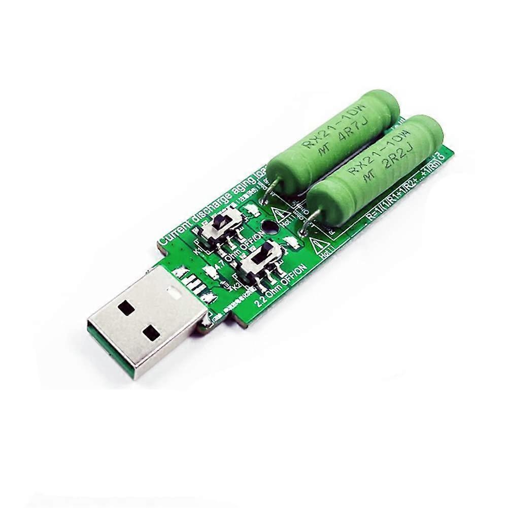
Electronic USB discharge load with switch-selectable parallel resistors — ideal for controlled USB load testing and capacity/discharge checks.
Key benefits
Simple selectable loads: switch between discrete resistances or combine them in parallel to produce three distinct load modes for versatile testing.
Accurate, repeatable discharge: use the included resistor options to create reliable, measurable loads for USB ports, power banks, and chargers.
High-power handling per resistor: each resistor is rated at 10 W, enabling sustained discharge tests without immediate overheating.
What it does (function and standout features)
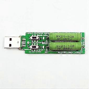
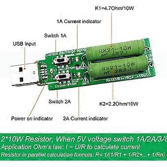
Selectable resistors arranged in a parallel topology and controlled by switches allow three effective resistance options: 2.2 Ω (10 W), 4.7 Ω (10 W), or both resistors used in parallel.
When both resistors are engaged in parallel the device produces a lower combined resistance and higher discharge current; at 5 V this combined mode can produce nearly 3 A of discharge current.
Switch-based selection gives fast, tool-free changes between load modes for bench testing and field use.
Compatibility and performance
Designed for USB/5 V systems. Use the device to apply a controlled resistive load to USB power sources, power banks, chargers, or USB ports.
Resistances and power ratings:
2.2 Ω at 10 W
4.7 Ω at 10 W
Both resistors in parallel (switch selectable) for the combined low-resistance mode
Use Ohm’s law to calculate actual current: I = V / R
Use the parallel resistance formula for multiple resistors: R = 1 / (1/R1 + 1/R2 + ... + 1/Rn)
Practical examples / use scenarios
Power bank capacity and discharge testing: apply a stable resistive load to measure how long a power bank sustains output at a chosen current.
USB charger and port verification: check voltage stability and thermal performance under known loads by switching between the available resistances.
Device troubleshooting and development: reproduce expected load conditions for firmware, battery management, or charging-circuit validation.
How to use (brief)
Connect the load to the USB 5 V output under test.
Select the desired resistor mode with the switches: 2.2 Ω, 4.7 Ω, or both in parallel.
Calculate expected current with I = V / R and verify it stays within the resistor power ratings (each resistor is 10 W).
Monitor voltage and temperature during extended tests.
Notes and practical considerations
Each resistor is rated 10 W; ensure the power dissipated (P = V * I = I^2 * R) stays within rating for extended tests or use intermittent testing to avoid overheating.
The device provides clearly defined resistance options; use the formulas above to compute exact resistance and current for your test conditions.
Specifications summary
Selectable resistor values: 2.2 Ω (10 W), 4.7 Ω (10 W), or both in parallel
Intended supply voltage: 5 V USB
Selection method: manual switches
Key equations provided: parallel resistance R = 1/(1/R1 + 1/R2 + ... + 1/Rn) and Ohm’s law I = V / R
This device delivers a compact, switch-selectable resistive load solution for USB discharge and testing needs, with clear resistance options and straightforward calculations for predictable, repeatable results.
-
Fruugo ID:
401723406-853825340
-
EAN:
484114820417